I’m the proud owner of a FDM 3D printer Anycubic i3 Mega. Even before receiving my printer, I was playing with the OctoPi distribution on a Raspberry Pi and I started to investigate the existing plugins.
PSU Control is an awesome plugin which is able to control your printer power supply from the OctoPrint web interface. To achieve that, you have to drive a relay module using a RPi GPIO output.
I already own a relay module and the project is only to build the required electronics and to create a small enclosure to protect the board.
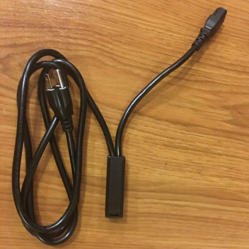
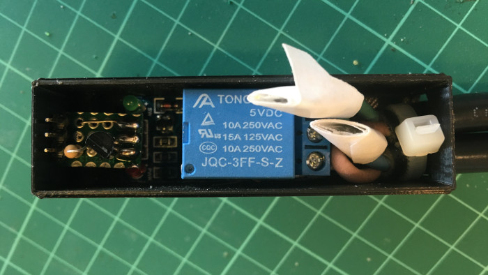
Here is how the result looks like
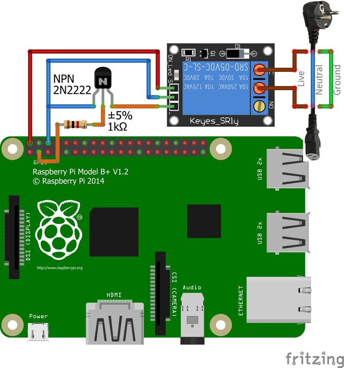
Electronics
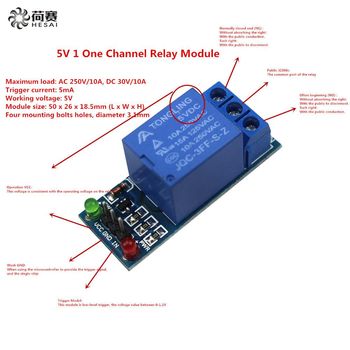 The relay module already contains some components to drive it and we don’t need lot of current but this module has
to be powered with 5V and GPIOs on the Raspberry Pi use 3.3V.
We have to setup a small board to trigger the relay properly.
The relay module already contains some components to drive it and we don’t need lot of current but this module has
to be powered with 5V and GPIOs on the Raspberry Pi use 3.3V.
We have to setup a small board to trigger the relay properly.
| NC state | NO state | |
|---|---|---|
| Relay not powered up | Closed | Open |
| In pin floating | Closed | Open |
| In pin connected to Vcc | Closed | Open |
| In pin connected to Ground | Open | Closed |
The idea is to use NC pins so the relay will act like a closed switch in all scenarios (RPi offline, GPIO not connected..) except when the GPIO drives the In pin to ground.
We need the following parts:
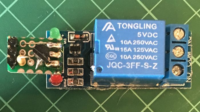
- Relay module (similar to JQC-3FF-S)
- Small PCB
- Standard NPN transistor (2N2222…)
- Resistor (between 1KΩ and 20KΩ should be ok)
The value of the resistor is not really important and is dependant of the transistor you use (the hFE value). The standard formula to find the correct value is as follow (full details here).
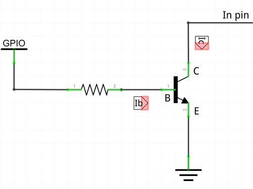
- Ic = 0.005A (it’s the current required to trigger the relay)
- Ib = Ic / hFE = 0.005 / ~200 = 0.000025 (it’s the minimal current required to saturate the transistor, hFE ~200 for 2N2222)
- (To be confortable, we can decide Ib = 0.0001A)
- Finaly R = (Vin - Vbe) / Ib = (3.3 - 0.7) / 0.0001 = 26000Ω = 26KΩ (Vbe is the voltage drop from the transitor)
I built this design on the smallest possible PCB and soldered it directly on the relay module (the most dirty way).
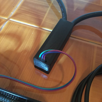
Enclosure
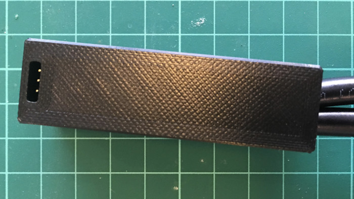
As we’re playing with AC high voltage, we need to protect this board from any external event (like my children). Using Fusion 360, I designed a small enclosure to protect the board. It’s a bit tight but everything fits properly on it.
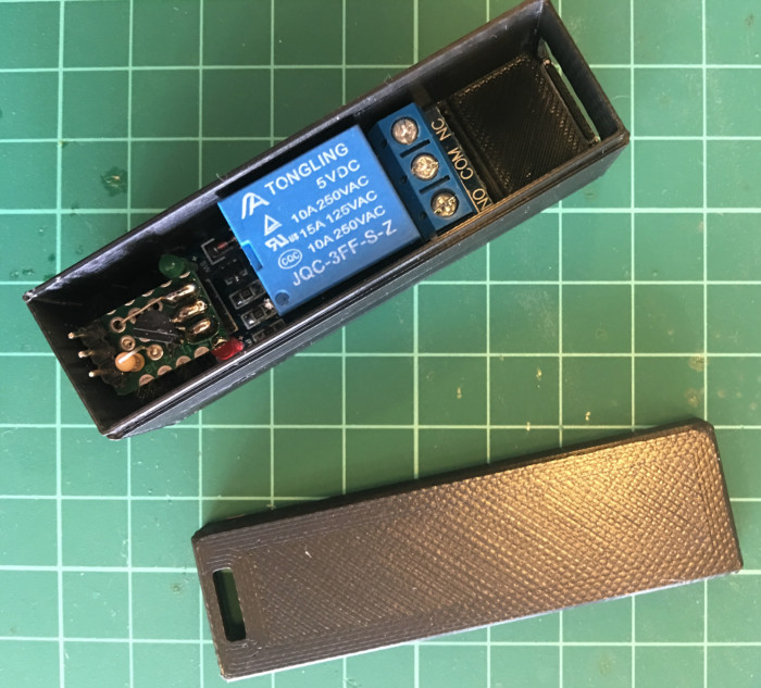
Then I cut the power outlet, inserted the two cords into the enclosure and did the appropriate connections on COM and NC pins.
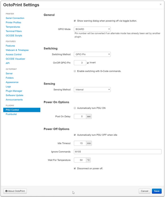
PSU Control